Why Choose a CT Transformer for Accurate Power Measurement?
Accurate power measurement begins with a dependable sensing method. In industrial panels, substations, and renewable energy systems, current transformers provide that foundation. A Ct Transformer reduces high primary current to a safer, measurable secondary signal. Meters and protection devices can then monitor energy flow without direct exposure to heavy conductors. Small errors matter. A minor ratio mismatch may affect billing, load analysis, or equipment protection. Practical commissioning experience shows that loose terminals, poor grounding, and excessive burden can distort otherwise reliable readings. These issues are easy to overlook during a rushed installation.
This article explores why engineers choose a Ct Transformer for precise power measurement. It considers transformation ratio, accuracy class, phase error, burden capacity, insulation, and long-term stability. Correct selection should reflect the actual operating current, fault conditions, and connected instruments. Recognized standards, including IEC 61869, offer useful guidance for design and testing. Qualified technicians should also verify polarity, wiring, torque, and calibration before energizing the system. A datasheet cannot reveal every installation problem. That limitation deserves attention. Even a high-quality transformer can perform poorly when incorrectly sized or installed. Field checks remain essential. Readers will find practical criteria for comparing models, reducing measurement uncertainty, and improving system reliability. The goal is not simply to choose the most expensive device. It is to choose a CT solution that fits the application, withstands real operating conditions, and produces trustworthy data over time.
What Is a CT Transformer?
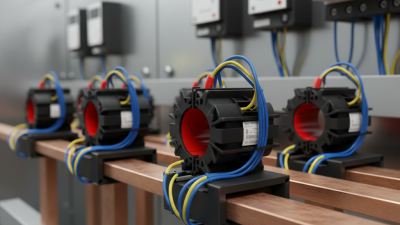
A current transformer, or CT transformer, is an instrument transformer that converts high line current into a smaller, measurable current. Its primary side is often the power conductor itself. A secondary winding then produces a proportional output, commonly 5 A or 1 A. This design lets meters and protection relays monitor heavy loads without carrying the full current.
The magnetic core performs the conversion. When current flows through the primary conductor, it creates a magnetic field. The secondary winding reproduces that field at a safer ratio. For example, a 400:5 CT converts 400 amperes into 5 amperes. The ratio must match the meter, or readings can drift. IEC 61869-2 specifies key requirements for accuracy, insulation, and performance under load.
The need is growing. The IEA Electricity 2024 report expects global electricity demand to rise by about 3.4% annually from 2024 to 2026. Its Grids and Secure Energy Transitions report also estimates that 80 million kilometres of grids must be added or refurbished by 2040. Accurate current measurement becomes less optional as networks expand.
Installation still deserves humility. A wrong polarity connection can reverse power readings. An overloaded burden can increase error. The secondary circuit must not be left open while energized; dangerous voltage may appear. In field work, technicians should verify the ratio, burden, phase relationship, and test results before trusting the display. CT transformers are precise, but not automatically perfect.
Why Choose a CT Transformer for Accurate Power Measurement?
A current transformer (CT) safely converts a high primary current into a proportional, measurable secondary current. The chart below shows an idealized 50 Hz AC waveform for a 100 A RMS primary current using a 20:1 CT ratio, producing a 5 A RMS secondary current.
The secondary current follows the primary waveform while remaining electrically isolated from the high-current circuit. In practical applications, measurement accuracy also depends on CT accuracy class, connected burden, frequency, and avoiding core saturation.
How Does a CT Transformer Measure Electrical Current?
Why Choose a CT Transformer for Accurate Power Measurement?
How Does a CT Transformer Measure Electrical Current?
A CT transformer measures current without placing the full load current through the meter. Its primary side is usually the existing power conductor. The conductor creates a magnetic field inside the CT’s iron core. That field induces a smaller current in the secondary winding. The secondary current follows a defined ratio, such as 400:5 amperes. A measuring device then converts this signal into a readable current value.
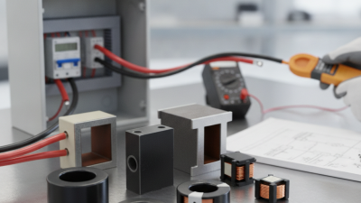
In field testing, an electrician may clamp the CT around a feeder cable and connect its secondary terminals to a meter. The meter reads the reduced current and calculates the primary current. A burden resistor controls the secondary load. Its value matters. Excessive burden can reduce accuracy and cause heating. Phase angle also affects power calculations, especially when measuring motors or other inductive equipment.
The method is reliable, but it is not flawless. I have seen incorrect readings caused by loose terminals, poor conductor positioning, and an unsuitable CT ratio. Core saturation can distort the waveform during heavy faults or short overloads. Never leave an energized CT secondary open. Dangerous voltage can develop. Use approved shorting facilities and follow qualified electrical procedures. Calibration should match the meter, wiring length, burden, and expected load range. Small installation details often decide whether the final measurement is trustworthy.
Why CT Transformers Provide Accurate Power Measurement
Why Choose a CT Transformer for Accurate Power Measurement?
A current transformer, or CT, converts high line current into a safer, measurable secondary current. This enables meters to monitor large loads without direct connection to high-energy conductors. Its value is precision. IEC 61869-2 defines accuracy classes, including 0.1, 0.2, and 0.5, for measurement transformers. A 0.2-class CT can limit its specified ratio error to roughly 0.2% under stated conditions. That difference matters during billing, load analysis, and equipment testing.
The U.S. Energy Information Administration reports that transmission and distribution losses remain near 5% of electricity supplied in recent annual data. CTs cannot remove these losses. They can, however, help locate abnormal demand and reveal mismatches between generated and consumed energy. In field commissioning, technicians often find that incorrect polarity, oversized ratios, or excessive secondary burden distort readings. Accuracy is not automatic. Temperature, saturation, wiring length, and poor connections still matter. I have seen a perfectly rated CT produce disappointing results because installation details were ignored.
Tips: Select the ratio close to the expected operating current. Confirm the meter burden against the CT rating. Check polarity before energizing. Record ambient temperature and test results. Review IEC 61869-2 and local metering requirements before acceptance. A small inspection mistake can become a costly data problem.
What Factors Affect CT Transformer Measurement Accuracy?
Why Choose a CT Transformer for Accurate Power Measurement?
What Factors Affect CT Transformer Measurement Accuracy?
A CT transformer can deliver dependable power measurements, but accuracy depends on more than its rated ratio. In field work, the first checks are often simple: ratio, burden, and wiring. A mismatch between the transformer and connected meter can create noticeable errors, especially when secondary leads run across a large panel. Keep leads short, secure, and correctly polarized. Small details matter.
Core saturation is another major concern. High fault currents or heavy temporary loads can push the magnetic core beyond its linear range. The output then becomes distorted, and the measured current may appear lower than reality. Selecting a suitable accuracy class helps, but it is not a complete solution. The expected current range, system frequency, and fault conditions must also be reviewed.
Temperature, loose terminals, and poor installation can gradually weaken measurement reliability. Harmonic-rich loads may introduce additional uncertainty because some transformers perform differently under distorted waveforms. Regular testing with calibrated equipment can reveal ratio errors and phase displacement before they affect operating decisions. In practice, even careful technicians can overlook the burden created by extra meters or long cables. That deserves a second check. No installation is perfect, and measurement records should include conditions, not only final readings.
How to Select and Use the Right CT Transformer
Why Choose a CT Transformer for Accurate Power Measurement?
How to Select and Use the Right CT Transformer
A CT transformer makes high-current measurement safer and more practical. The right model depends on the circuit, not only the expected current. Measure the normal load and possible peak current before selecting it. A 400-ampere circuit may need a different ratio than its nameplate suggests. Leave reasonable headroom, but avoid excessive oversizing. A weak signal can reduce measurement resolution. An oversized CT can create disappointing accuracy at light loads.
Check the transformation ratio, accuracy class, rated burden, frequency, and insulation level. The burden includes the meter, terminals, and cable resistance. Long wires add burden quickly. Keep the CT close to the measuring device when possible. Measurement CTs and protection CTs serve different purposes. Do not replace one with the other without reviewing the application. That mistake is easy to make. I have seen technicians choose by current ratio alone, then discover unstable readings during low-demand periods.
Installation quality matters just as much. Match the polarity marks and pass the conductor through the window correctly. Confirm the secondary wiring before energizing the primary. Never leave an energized CT secondary open. Use an approved shorting terminal during maintenance. After installation, compare readings with a calibrated reference meter under several loads. Record the ratio, wiring route, test conditions, and observed error. The first reading may look fine, yet loose terminals can create problems later. Recheck connections after thermal cycling, especially in crowded panels. Accurate measurement is a process, not merely a component choice.